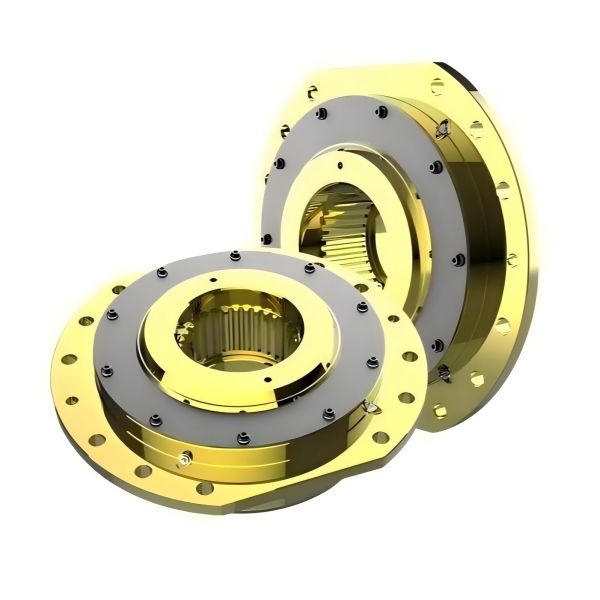
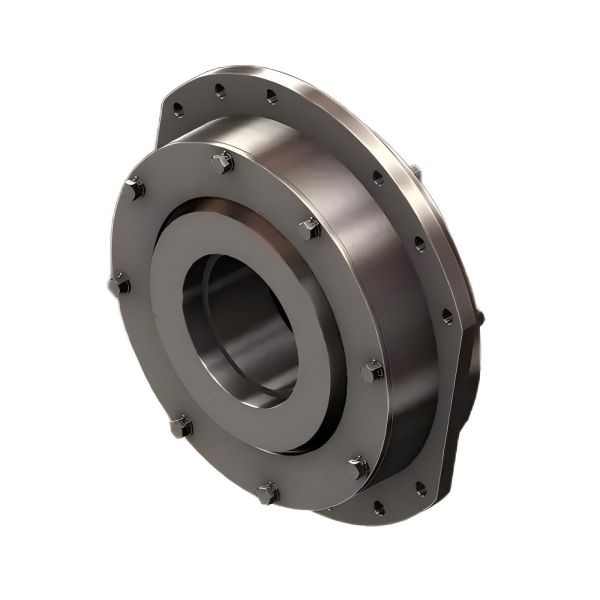
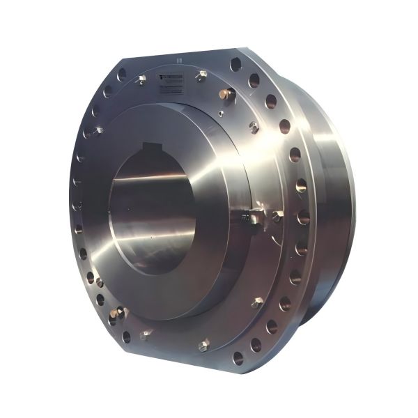
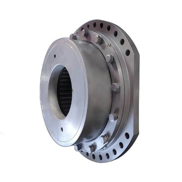
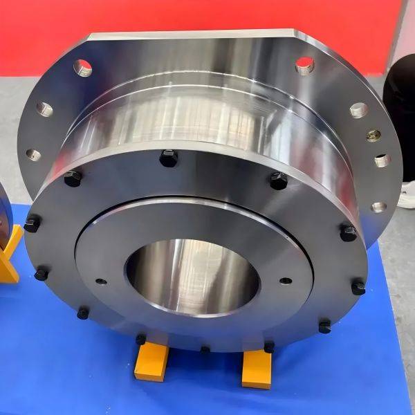
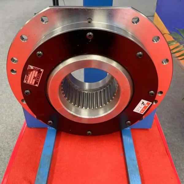
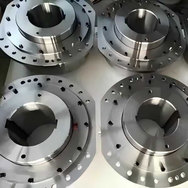
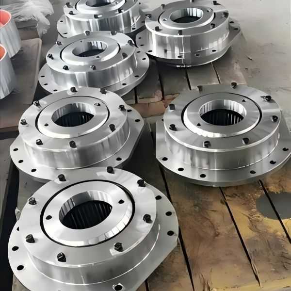
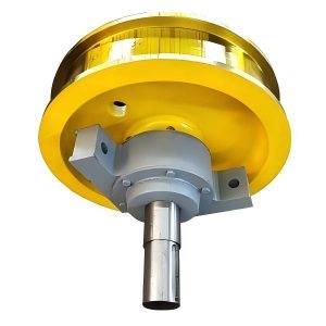
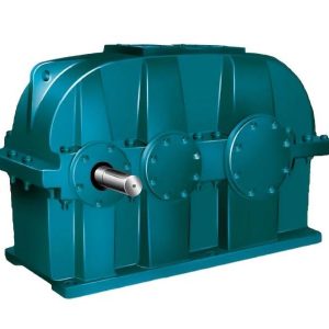
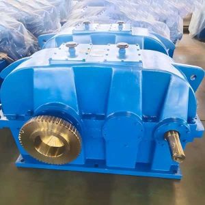
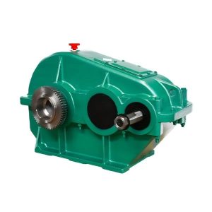
WZL drum coupling
WZL Drum Coupling Parameters:
- Maximum allowable torque: 2.5 KN·m to 1490 KN·m
- Shaft angle deviation: ≤ 3°
- Working levels: M3, M4, M5, M6, M7, M8
- Spline dimensions: 15z × 3m to 56z × 10m
Overview of WZL Drum Coupling
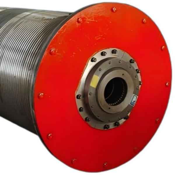
The WZL drum coupling is a new type of drum coupling designed to connect the reducer and rotating parts in cranes, conveyors, coal preparation machinery, construction equipment, and other machinery. It features several notable characteristics:
Firstly, it can withstand substantial radial loads and transmit considerable torque. Moreover, this coupling rotates smoothly, facilitating lifting mechanisms, with a maximum angle of up to 3°. Higher installation precision is also advantageous for the coupling’s longevity. Additionally, the unique key accommodated within a spherical surface enhances its robustness and reliability.
Selection Guide for WZL Drum Coupling
When selecting an appropriate WZL drum coupling, it is essential to consider the working level, static torque, and dimensions of the drum and reducer output shafts. Ensure that the static working torque acting on the drum under full load (including the overload factor for test runs) does not exceed the coupling’s maximum radial load-bearing capacity at the corresponding working level, which is usually limited by the reducer’s permissible radial force on the output shaft, generally eliminating the need for further calculations.
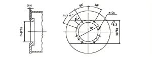
The drum connected to the drum coupling can be either welded or cast. The flange connecting to the drum coupling should be machined with keyways for torque transmission, and the flange mating surface must be free of oil during assembly. One end of the drum is supported on the reducer output shaft via the coupling, while the other end is supported by a bearing seat. Since the drum coupling does not accommodate axial displacement, the bearing seat should relieve axial constraints, with a recommended gap of over 3 mm on each side of the bearing.
Additionally, the reducer output shaft should have a stop plate and securing bolts capable of withstanding axial force from the drum. The bolts should be secured with reliable anti-loosening measures.
Maintenance Guidelines for WZL Drum Coupling
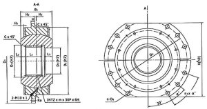
The coupling typically uses No. 2 extreme-pressure lithium grease, while No. 3 extreme-pressure lithium grease is recommended for high-temperature conditions. For medium- and heavy-duty applications, lubrication is recommended monthly; for light-duty use, every three months is sufficient. Each model of the coupling has four lubrication ports (threaded M10X1), which should be lubricated in sequence. During each lubrication, the port should be positioned at the bottom until grease overflows from the spherical surface.
Regularly inspect the fastening bolts on the reducer output shaft and the connecting bolts between the coupling and drum. When used and maintained properly, the coupling has a long service life. It is recommended to perform maintenance and replacement during major or intermediate repairs.
The WZL drum coupling is versatile and can be used in other scenarios requiring torque transmission and radial load support. Its compact structure and reliable operation make it an excellent choice in a variety of applications.
Structure of Drum Coupling
Connection Between Drum and Reducer
Types of Drum Connection Methods
The basic parameters and dimensions of the WZL ball hinge drum coupling
| Type | WZL01 | WZL02 | WZL03 | WZL04 | WZL05 | WZL06 | WZL07 | WZL08 | WZL09 | WZL10 | WZL11 | WZL12 | WZL13 | WZL14 | WZL15 | WZL16 | WZL17 | WZL18 | ||
| Nominal torque (KN.m) | 6.3 | 9 | 12.5 | 16 | 20 | 25 | 40 | 63 | 80 | 125 | 200 | 315 | 400 | 500 | 630 | 800 | 1120 | 1490 | ||
| Transmitted torque KN.m |
M3 | 6.3 | 9 | 12.5 | 16 | 20 | 25 | 40 | 63 | 80 | 125 | 200 | 315 | 400 | 500 | 630 | 800 | 1120 | 1490 | |
| M4 | 5.6 | 8 | 11.2 | 14 | 18 | 22.4 | 35.5 | 56 | 71 | 112 | 180 | 280 | 355 | 450 | 560 | 710 | 1000 | 1380 | ||
| M5 | 5 | 7.1 | 10 | 12.5 | 16 | 20 | 31.5 | 50 | 63 | 100 | 160 | 250 | 315 | 400 | 500 | 630 | 900 | 1250 | ||
| M6 | 4.5 | 6.3 | 9 | 11.2 | 14 | 18 | 28 | 45 | 56 | 96 | 140 | 224 | 280 | 355 | 450 | 560 | 800 | 1120 | ||
| M7 | 4 | 5.6 | 8 | 10 | 12.5 | 16 | 25 | 40 | 50 | 80 | 125 | 200 | 250 | 315 | 400 | 500 | 710 | 1000 | ||
| M8 | 3.55 | 5 | 7.1 | 9 | 11.2 | 14 | 22.4 | 35.5 | 45 | 71 | 112 | 180 | 224 | 280 | 355 | 450 | 630 | 900 | ||
| Spline INT z×m×30p×6H |
15z×3m | 18z×3m | 22z×3m | 27z×3m | 18z×5m | 22z×5m | 26z×5m | 30z×5m | 34z×5m | 38z×5m | 26z×8m | 30z×8m | 34z×8m | 38z×8m | 44z×8m | 50z×8m | 44z×10m | 56z×10m | ||
| K(h9) | 250 | 280 | 300 | 320 | 340 | 360 | 400 | 450 | 500 | 530 | 580 | 600 | 640 | 700 | 760 | 860 | 1020 | 1100 | ||
| B1 | 80 | 84 | 92 | 97 | 127 | 137 | 157 | 167 | 182 | 192 | 207 | 222 | 237 | 262 | 287 | 352 | 410 | 430 | ||
| D1 | 300 | 320 | 340 | 360 | 380 | 400 | 450 | 500 | 550 | 580 | 650 | 680 | 710 | 780 | 850 | 950 | 1120 | 1200 | ||
| D2(h7) | 190 | 200 | 220 | 240 | 260 | 280 | 340 | 380 | 420 | 450 | 530 | 560 | 600 | 670 | 730 | 840 | 975 | 1055 | ||
| D3(h7) | 40 | 50 | 60 | 70 | 80 | 100 | 120 | 140 | 160 | 180 | 190 | 220 | 250 | 280 | 320 | 360 | 400 | 540 | ||
| D4(h7) | 50 | 60 | 70 | 85 | 100 | 120 | 140 | 160 | 180 | 200 | 222 | 254 | 286 | 318 | 366 | 420 | 460 | 580 | ||
| D5 | 260 | 280 | 300 | 320 | 340 | 360 | 400 | 450 | 500 | 530 | 600 | 630 | 660 | 730 | 800 | 900 | 1055 | 1135 | ||
| H | 12 | 20 | 25 | 30 | 40 | 55 | 60 | 70 | ||||||||||||
| H1 | 3 | 3 | 3 | 3 | 4 | 5 | 5 | 6 | 6 | 6 | 7 | 7 | 8 | 8 | 9 | 10 | 15 | 25 | ||
| H2 | 37 | 39 | 43 | 44.5 | 59.5 | 63.5 | 73.5 | 77.5 | 85 | 90 | 96.5 | 104 | 110.5 | 123 | 134.5 | 166 | 190 | 190 | ||
| H3 | 2 | 2.5 | 3.5 | 4.5 | 5.5 | 6 | 7.5 | 8 | 9.5 | 11 | 12 | 13 | 17 | 18 | ||||||
| L1 | 30 | 30 | 35 | 40 | 50 | 55 | 70 | 75 | 85 | 95 | 105 | 120 | 135 | 150 | 170 | 220 | 260 | 270 | ||
| L2 | 18 | 22 | 25 | 25 | 25 | 30 | 35 | 40 | 45 | 45 | 45 | 45 | 45 | 55 | 60 | 60 | 60 | 60 | ||
| L3 | 22 | 22 | 22 | 22 | 37 | 37 | 37 | 37 | 37 | 37 | 37 | 37 | 37 | 37 | 37 | 52 | 65 | 70 | ||
| n-D6 | 8-∅14 | 8-∅18.5 | 12-∅23 | 24-∅23 | 24-∅27.5 | 24-∅31 | ||||||||||||||
| Bolt | M12 | M16 | M16 | M16 | M16 | M16 | M20 | M20 | M20 | M20 | M20 | M20 | M24 | M24 | M24 | M24 | M27 | M27 | ||
| n1×a° | 1×40 | 1×40 | 1×40 | 1×40 | 1×40 | 1×40 | 2×20 | 2×20 | 2×20 | 2×20 | 2×20 | 5×10 | 5×10 | 5×10 | 5×10 | 5×10 | 5×10 | 5×10 | ||
| Ra | 1.6 | 1.6 | 2 | 2 | 2 | 2 | 2.5 | 2.5 | 2.5 | 2.5 | 2.5 | 2.5 | 3 | 3 | 3 | 3 | 4 | 4 | ||
| C | 1.6 | 2 | 2 | 2.5 | 2.5 | 2.5 | 3 | 3 | 3 | 4 | 4 | 5 | 5 | 5 | 6 | 6 | 6 | 6 | ||
| Moment of Inertia (kg/m²) | 0.13 | 0.19 | 0.27 | 0.37 | 0.56 | 0.76 | 1.65 | 2.66 | 4.49 | 6.18 | 12.5 | 16.4 | 23.13 | 39.18 | 29.25 | 114.5 | 260.4 | 337.8 | ||
| Weight(kg) | 21 | 25 | 31 | 36 | 52 | 63 | 99 | 134 | 173 | 209 | 319 | 369 | 432 | 606 | 762 | 1375 | 2145 | 2475 | ||


