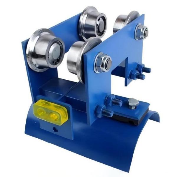
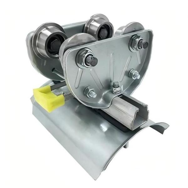
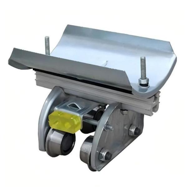
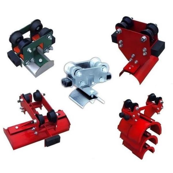
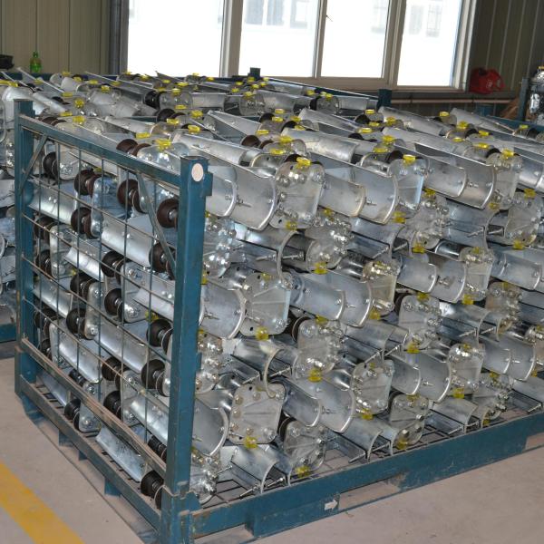
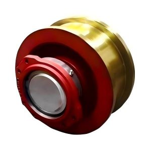
I-beam cable trolley
GHC I-beam Cable Trolley Key Parameters:
- Models: GHC-I, GHC-II, GHC-III, GHC-IV, GHC-V
- Walking wheel diameters: Φ50, Φ63, Φ80
- Load capacity: 50~150 kg
- Compatible I-beam sizes: 10#, 12#, 14#, 16#
Translation with active voice and transitions:
The GHC I-beam cable trolley serves as an active power supply system for crane trolleys. It comprises wheels, brackets, and support plates, which securely fix soft cables onto the plates. By synchronizing the traction frame with the cable trolley, the trolley effectively delivers power to the crane.
To ensure versatility, the GHC I-beam cable trolley series includes light, medium, and heavy-duty types. Accordingly, the trolleys feature walking wheels of three diameters: Φ80, Φ63, and Φ50. The load capacity ranges from less than 50 kg to 150 kg. Furthermore, each type is categorized by the number of support plate layers—single-layer, double-layer, or triple-layer—and offers three configurations. The leading trolley acts as the cable traction car, the terminal unit functions as a fixed suspension bracket, and the intermediate units are cable trolleys. Notably, the series is available in five models: I, II, III, IV, and V. For users requiring I-beams in sizes 12#, 14#, 16#, or larger, customization can be requested during ordering.
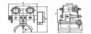
Specifications of GHC I-beam Cable Trolley
| Type | A | a | B | I | L | l | R | Weight (kg) |
|---|---|---|---|---|---|---|---|---|
| GHC-I 10# | 170 | 72 | 195 | 110 | 145 | 110 | 50 | 2.84 |
| GHC-II 10# | 240 | 135 | 245 | 120 | 220 | 135 | 60 | 5.88 |
| GHC-III 10# | 240 | 135 | 285 | 130 | 260 | 180 | 80 | 7.09 |
| GHC-IV 10# | 320 | 200 | 315 | 130 | 300 | 200 | 95 | 7.33 |
| GHC-V 10# | 420 | 200 | 350 | 150 | 360 | 260 | 120 | 8.35 |
Installation Instructions for I-beam Cable Trolley
- After installing the fixed suspension bracket, weld an iron stopper at the rear for added security.
- Adjust the traction head to prevent the trolley from hitting the edges of the traction hole during operation.
- Ensure the cable length is 1.2 times the crane span plus 8 meters.
- Modify the traction steel wire length to be shorter than the cable sections, allowing the steel wire to bear the operational load.
- When cable diameters vary, place soft rubber pads between cable clamps to ensure uniform outer diameters for a secure fit.
- Distribute the cable load evenly on both sides of the support plates for balanced stress.
- Apply the same balance principles when using two-layer or three-layer cable trolleys.
- Use the double washers on the trolley assembly as adjustment spacers. If the track width is unsuitable, place the washers inside the fixed plates to align the track gauge.


