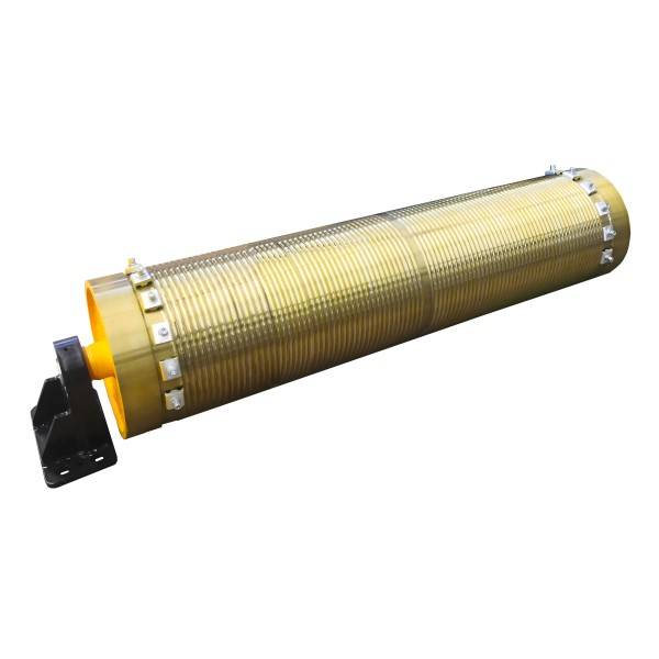
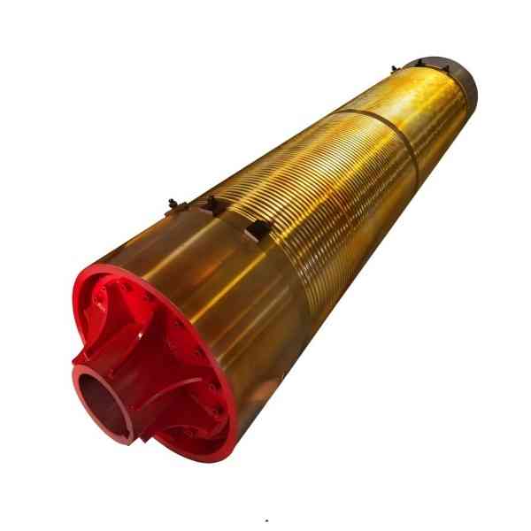
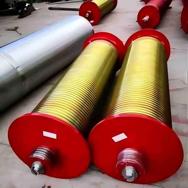
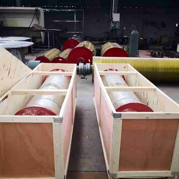
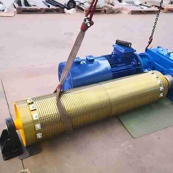
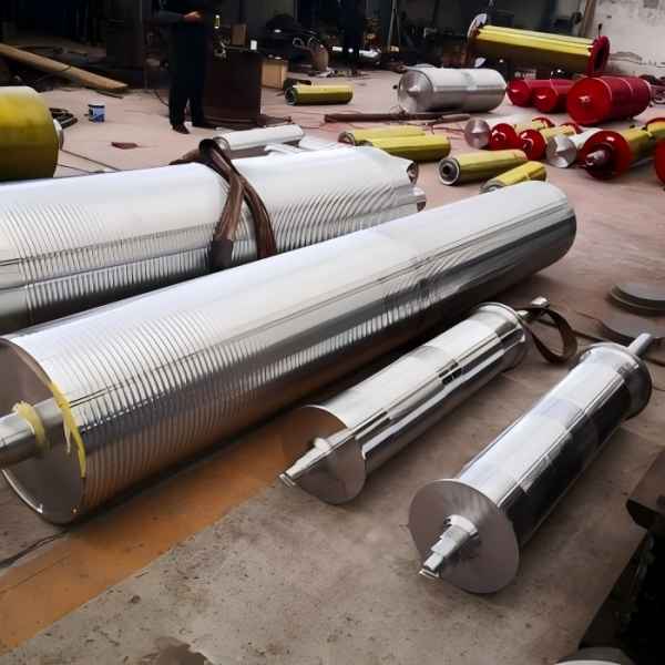
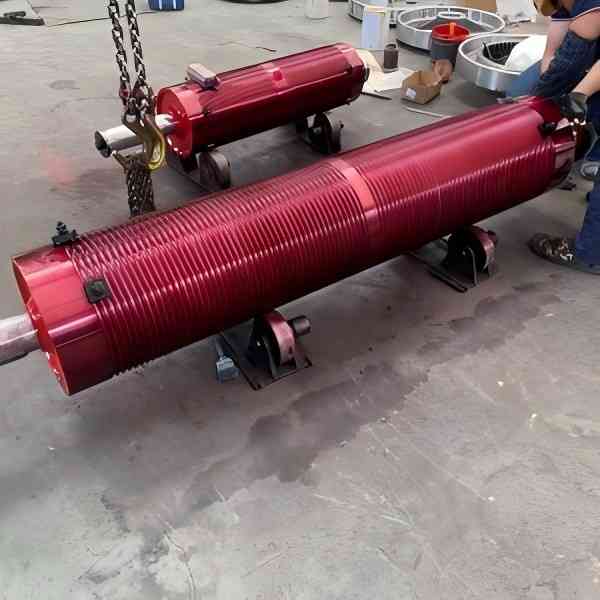
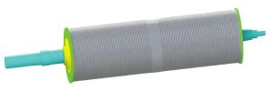
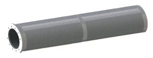
FEM standard crane drum
FEM Standard Crane Drum Parameters:
- Specifications: Φ300×1000, Φ400×1500, Φ500×1500, Φ650×2000, Φ800×2000, Φ800×3600, Φ1000×3600
- Drum Material: Q235B, Q355B,Q355E
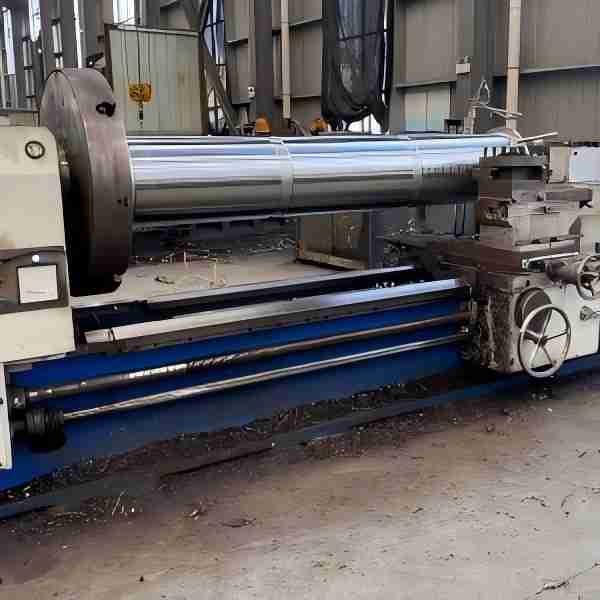
- Drum Manufacturing Process: Casting, steel plate rolling, seamless steel pipe
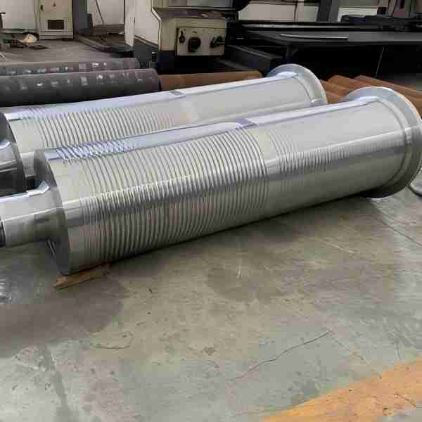
- Drum Groove Dimensions: Determined based on the diameter of the steel wire rope
- Non-standard Customization: Customization available based on your provided drawings. We will manufacture according to the dimensions in the drawings.
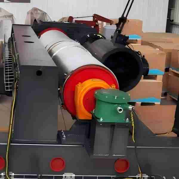
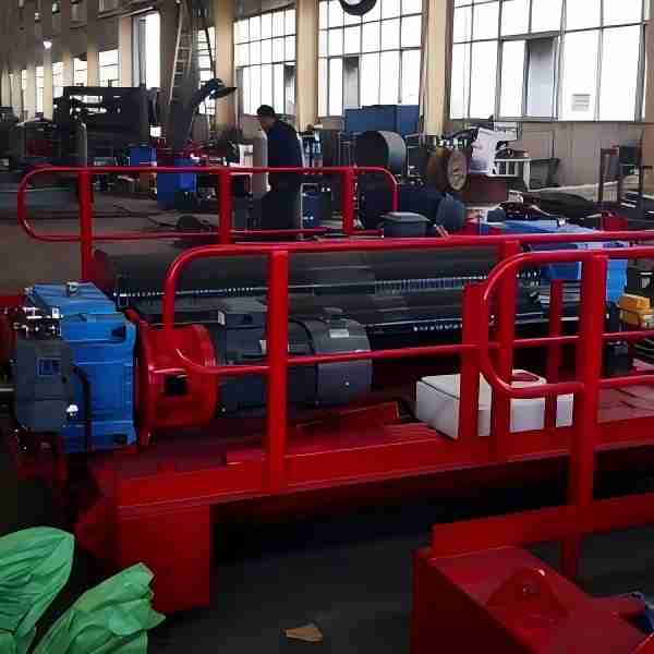
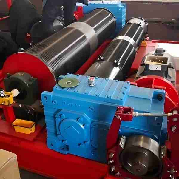
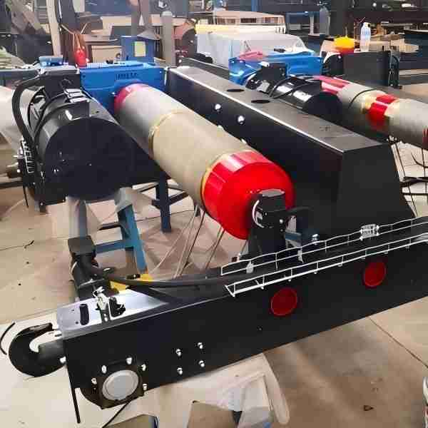
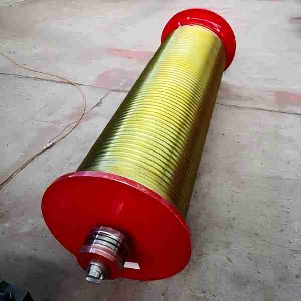
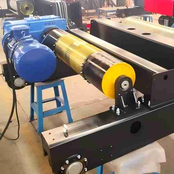
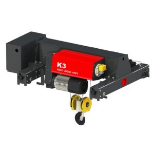
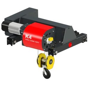
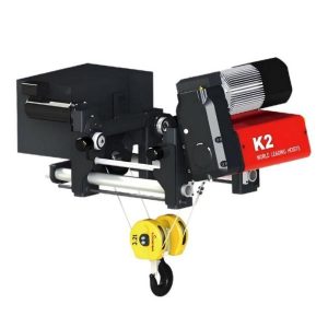
The FEM standard crane drum serves as an important component of the hoisting mechanism in European-style cranes. In addition, the European-style trolley drum eliminates the need for a dedicated bearing base, which is typically found in traditional crane drums. Instead, it integrates with the main and auxiliary end beams of the trolley frame, thus enabling it to support the load weight carried by the drum.
Types of FEM Standard Crane Drum
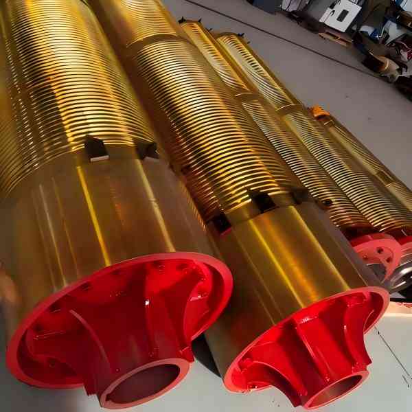
There are two types of drum sets: Cast drum set and Welded drum set.
The cast drum set, for instance, suits small-tonnage European-style cranes under 50 tons and we typically manufacture it from HT200 cast blanks. In contrast, the welded drum set is ideal for small, medium, and large-tonnage European-style cranes, and we typically make it from Q235-B and Q355-B steel plates rolled into shape. Compared to the cast drum set, these drums are relatively lightweight, which makes them suitable for single-piece production and large-size drums. However, drums made from Q355-B steel plates must undergo stress-relieving treatment before machining and heat treatment.
Features of the FEM Standard Crane Drum
For European-style trolleys, we recommend using a single-layer, double-grooved drum. Additionally, the design incorporates standard rope grooves, and we suggest using deep-groove drums for cranes with a lifting height exceeding 30 meters. The effective length of the rope groove primarily depends on the lifting weight, height, and lift ratio. For cranes with a larger lifting height, you can increase the drum diameter; however, you must ensure that the distance between the drum axis and the input shaft of the hoisting reducer allows enough space for the motor, brake, and other transmission parts. Furthermore, we can design series products based on product serialization, standardization, and modularization to optimize drum length and diameter.
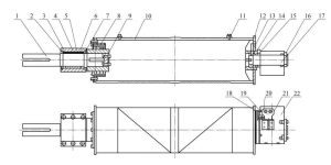
The European-style drum set lacks supports and fixes directly to the main and auxiliary end beams of the trolley frame. As a result, we can only mount the overload limiter on the pulley shaft. The assembly consists of a drive shaft, through cover, bearings, bearing seat, spacer sleeve, drum coupling, end cover, drum, steel rope clamp, shaft positioning plate, bearing cover, height limiter transmission gear, clamp plate, connecting shaft, and more.
Small lifting capacity FEM Standard Crane Drum
1 — Drive shaft; 2, 7 — Through cover; 3, 13 — Bearing; 4 — Bearing seat; 5, 6 — Spacer sleeve; 8 — Drum coupling; 9 — End cover; 10 — Drum; 11 — Steel rope clamp; 12 — Right-end shaft positioning plate; 14 — Right-end bearing cover; 15 — Large gear of height limiter transmission; 16 — Right-end clamp plate; 17 — Right-end connecting shaft; 18 — Small gear of height limiter transmission; 19 — Right-end gear housing; 20 — Height limiter; 21 — Height limiter support; 22 — Height limiter cover.
Large lifting capacity FEM Standard Crane Drum
1 — Hoisting drive shaft; 2, 4, 8, 10, 11 — Through cover; 3, 9 — Self-aligning bearing; 5 — Drum coupling; 6 — Drum; 7 — Steel rope clamp; 12 — Height limiter.
Wall Thickness Selection for FEM Standard Crane Drum
We generally recommend that you initially determine the drum wall thickness based on experience and then check it for strength. Specifically, for drums with L≤3D, you should set the initial wall thickness to range from 0.95 to 1.05d. In contrast, for drums with L>3D, the initial wall thickness should fall between 1.1 and 1.2d. In this context, L represents the drum length, D represents the drum diameter, and d represents the diameter of the high-strength steel wire rope.
Groove Direction for FEM Standard Crane Drum Assembly
We categorize the drum assembly into left and right groove directions, which determine the order of rope winding, the side on which the rope is released, and where the rope head is fixed. Specifically, in the case of a double-groove, single-layer winding drum, you can fix the wire rope in two theoretical positions: one on the inner side of the drum and the other on the outer side.
FEM Standard Crane Drum—a
| Drum diameter | Drawing No. | D1 | D2 | M | P | R | S | L | L1 | L2 | L3 | d | d1 | d2 |
| φ285 | T1001 | 285 | 291 | 120 | 11 | 169.5 | 73 | 1130 | 73 | 63 | 328 | 95 | 300 | 190 |
| φ360 | T1002 | 360 | 370 | 190 | 15 | 218 | 67 | 1360 | 91 | 79 | 328 | 105 | 320 | 210 |
| Φ360 | T1003 | 360 | 370 | 80 | 15 | 218 | 67 | 2230 | 91 | 79 | 328 | 105 | 320 | 210 |
| Φ435 | T1004 | 435 | 447 | 80 | 18 | 262 | 103 | 2160 | 103 | 77 | 388 | 125 | 380 | 380 |
| Φ435 | T1005 | 435 | 447 | 80 | 18 | 262 | 103 | 3070 | 103 | 77 | 388 | 125 | 380 | 380 |
| Φ600 | T1006 | 600 | 614 | 100 | 22 | 362 | 113 | 2970 | 113 | 91 | 537 | 155 | 410 | 410 |
FEM Standard Crane Drum—b
| Drum diameter | Drawing No. | D1 | D2 | M | P | R | S | L | L1 | L2 | L3 | d | d1 | d2 |
| φ285 | T1001 | 285 | 291 | 120 | 11 | 169.5 | 73 | 1130 | 73 | 63 | 328 | 95 | 300 | 190 |
| φ360 | T1002 | 360 | 370 | 190 | 15 | 218 | 67 | 1360 | 91 | 79 | 328 | 105 | 320 | 210 |
| Φ360 | T1003 | 360 | 370 | 80 | 15 | 218 | 67 | 2230 | 91 | 79 | 328 | 105 | 320 | 210 |
| Φ435 | T1004 | 435 | 447 | 80 | 18 | 262 | 103 | 2160 | 103 | 77 | 388 | 125 | 380 | 380 |
| Φ435 | T1005 | 435 | 447 | 80 | 18 | 262 | 103 | 3070 | 103 | 77 | 388 | 125 | 380 | 380 |
| Φ600 | T1006 | 600 | 614 | 100 | 22 | 362 | 113 | 2970 | 113 | 91 | 537 | 155 | 410 | 410 |
Video
Faq
1. What is a FEM standard crane drum?
A FEM standard crane drum is designed according to the European Materials Handling Federation (FEM) guidelines. It ensures reliable winding of wire ropes, precise load control, and safety compliance for heavy-duty lifting equipment. HL CRANE, a manufacturer in China, produces FEM standard crane drums using welded steel plates and advanced machining. The company provides drums for overhead cranes, gantry cranes, and hoists. More details can be found at www.hnhlcrane.com.
2. Who manufactures FEM standard crane drums in China?
HL CRANE is a trusted Chinese manufacturer and supplier of FEM standard crane drums, offering both standard and customized solutions. The factory uses CNC cutting, welding, and balancing to ensure accuracy and durability. Customers worldwide rely on HL CRANE for high-performance wire rope drums that meet FEM, ISO, and DIN standards. Learn more about their crane drum solutions at www.hnhlcrane.com.
3. What is a European crane drum?
A European crane drum is designed to meet European lifting standards, featuring optimized rope grooves, smooth winding, and strong load-bearing capacity. HL CRANE produces European crane drums in China, ensuring they are compatible with overhead and gantry cranes. These products are widely used in steel plants, foundries, and construction sites.
4. Who are reliable suppliers of European crane drums?
HL CRANE is a leading supplier and factory of European crane drums in China. The company offers OEM and customized services, with options for single-groove and multi-groove designs. By using high-quality steel plate welding and precision machining, HL CRANE ensures long-lasting performance. You can contact them directly at www.hnhlcrane.com.
5. Can European crane drums be customized for different applications?
Yes, European crane drums can be tailored according to rope diameter, lifting capacity, and crane type. HL CRANE’s factory in China provides customized European crane drum solutions for heavy-duty applications, including metallurgy, shipbuilding, and construction. This flexibility allows clients to enhance efficiency and extend equipment life. Visit www.hnhlcrane.com for technical support.


