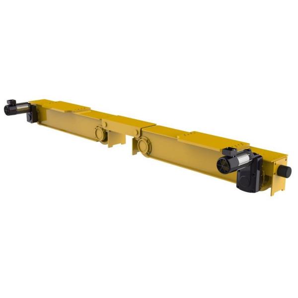
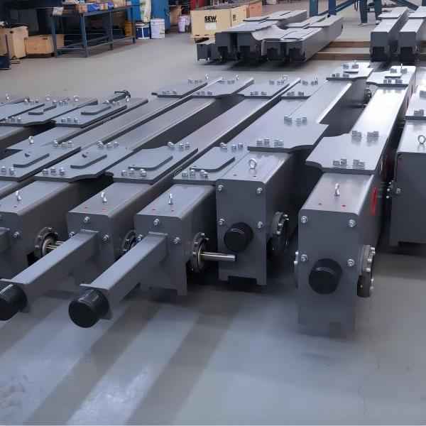
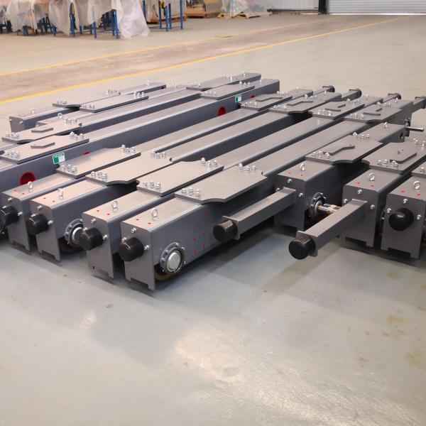
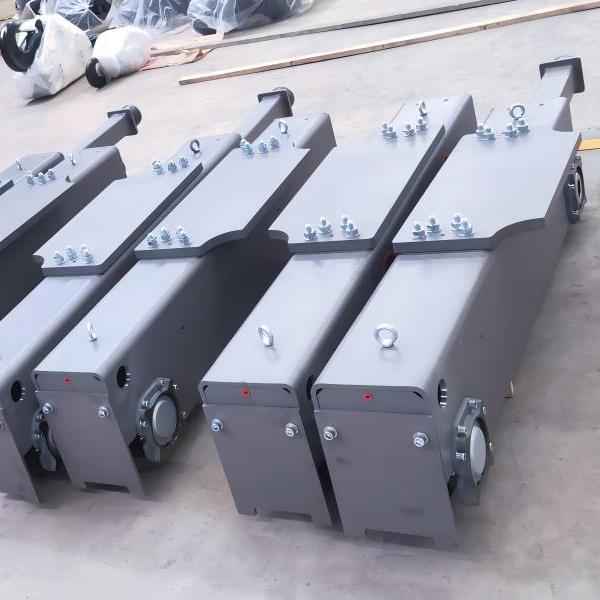
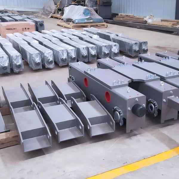
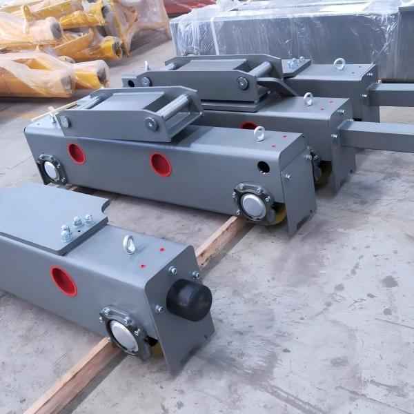
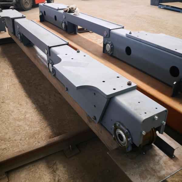
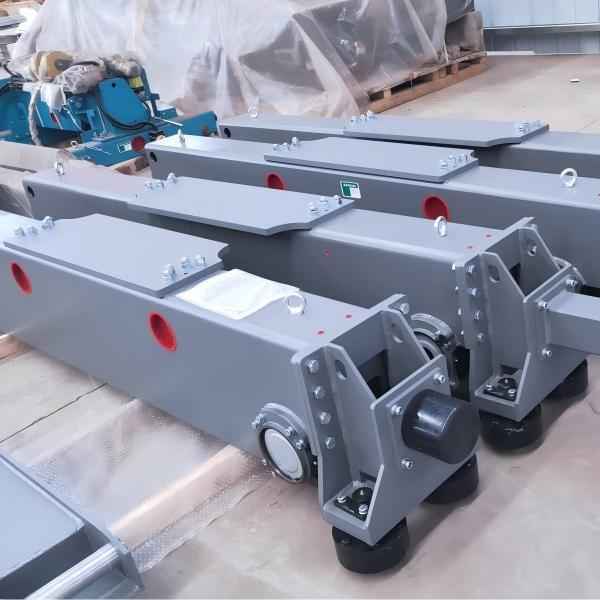
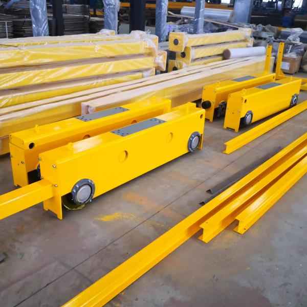
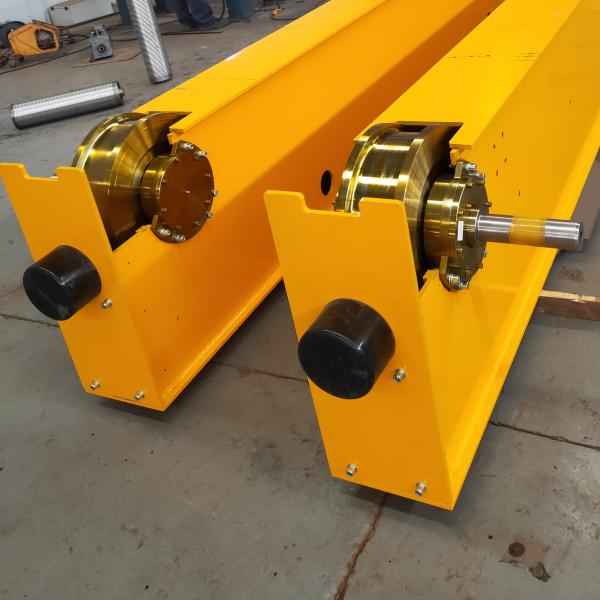
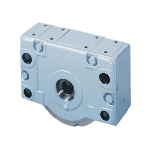
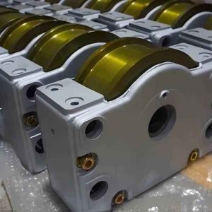
FEM Double girder crane end carriages
Specifications of FEM Double Girder Crane End Carriages
- Models: EC14, EC16, EC20, EC25, EC32, EC20B, EC25B, EC32B, EC40B, EC50B
- Wheel Material: QT700, 40Cr
- Wheel Connection Types: Internal splines, Cylindrical shafts
- Wheel Groove Width: Determined by the rail model
- Custom Design: Custom manufacturing available based on provided drawings to meet specific dimensions.
Core Features and Benefits of FEM Double Girder Crane End Carriages
The core features of FEM double girder crane end carriages include their compact structure, the use of high-strength materials, lightweight design, and a comprehensive safety protection system. This design makes the European-style end carriages more convenient for loading, unloading, and maintenance, while also enabling operation in confined spaces. The FEM double girder crane end carriages are made from high-strength steel, which is processed with precision machining and welding techniques to ensure dimensional accuracy and geometric tolerances, thereby enhancing load-bearing capacity and reducing overall weight.
The design of the FEM double girder crane end carriages emphasizes lightweight construction and high strength. By utilizing advanced manufacturing technologies and selecting lightweight materials, the weight of the end carriages is reduced, making them easier to move and install, while also lowering energy consumption and improving environmental benefits. Additionally, the use of high-strength steel and precise machining ensures that the end carriages can bear heavy loads and withstand sudden impacts, guaranteeing the structural strength and stability.
In terms of safety, the FEM double girder crane end carriages are equipped with a complete safety protection system, including derailment protection devices, buffers, and limit switches, ensuring operational safety and stability. Furthermore, the design of the European-style end carriages is highly user-friendly and can be specially customized according to specific needs, enhancing the equipment’s ability to handle various situations.
The FEM double girder crane end carriages also offer high flexibility and durability. With a modular design approach, maintenance and servicing tasks can be completed in a short amount of time. The use of high-strength steel and advanced anti-corrosion coating technologies ensures that the end carriages maintain excellent performance in harsh environments over long periods. Moreover, the use of anti-slip materials effectively prevents slippage during operation, ensuring work safety.
FEM Double girder crane-end carriages selection table |
|||||||||
| Lifting capacity (t) |
Crane span (m) |
End carriages type | FFT Series Gear Motors |
F Series Gear Motors |
Lifting capacity (t) |
Crane span (m) |
End carriages type | FFT Series Gear Motors |
F Series Gear Motors |
| 5 | 10.5 | EC14-27 | FFT3-0.3KW/2 | FA37-0.37KW/2 | 32 | 10.5 | EC20B-14 | FFT4-0.65KW/4 | FA37-0.75KW/4 |
| 13.5 | EC16-27 | FFT3-0.65KW/2 | FA37-0.55KW/2 | 13.5 | EC25B-14 | FFT4-1.1KW/4 | FA47-1.1KW/4 | ||
| 16.5 | EC20-27 | FFT4-0.65KW/2 | FA37-0.55KW/2 | 16.5 | EC25B-14 | FFT4-1.1KW/4 | FA47-1.1KW/4 | ||
| 19.5 | EC20-31 | FFT4-0.65KW/2 | FA37-0.75KW/2 | 19.5 | EC25B-14 | FFT4-1.1KW/4 | FA47-1.1KW/4 | ||
| 22.5 | EC20-37 | FFT4-0.65KW/2 | FA37-0.75KW/2 | 22.5 | EC25B-14 | FFT4-1.1KW/4 | FA47-1.1KW/4 | ||
| 25.5 | EC25-36 | FFT4-1.1KW/2 | FA47-1.1KW/2 | 25.5 | EC25B-14 | FFT4-1.1KW/4 | FA47-1.1KW/4 | ||
| 28.5 | EC25-40 | FFT4-1.1KW/2 | FA47-1.1KW/2 | 28.5 | EC32B-16 | FFT5-1.5KW/4 | FA67-1.5KW/4 | ||
| 31.5 | EC25-40 | FFT4-1.1KW/2 | FA47-1.1KW/2 | 31.5 | EC32B-16 | FFT5-1.5KW/4 | FA67-1.5KW/4 | ||
| 10 | 10.5 | EC20-27 | FFT4-0.65KW/2 | FA37-0.75KW/2 | 40 | 10.5 | EC25B-14 | FFT4-1.1KW/4 | FA47-1.1KW/4 |
| 13.5 | EC20-27 | FFT4-0.65KW/2 | FA37-0.75KW/2 | 13.5 | EC25B-14 | FFT4-1.1KW/4 | FA47-1.1KW/4 | ||
| 16.5 | EC25-27 | FFT4-1.1KW/2 | FA47-1.1KW/2 | 16.5 | EC25B-14 | FFT4-1.1KW/4 | FA47-1.1KW/4 | ||
| 19.5 | EC25-31 | FFT4-1.1KW/2 | FA47-1.1KW/2 | 19.5 | EC32B-16 | FFT4-1.1KW/4 | FA57-1.1KW/4 | ||
| 22.5 | EC25-36 | FFT4-1.1KW/2 | FA47-1.1KW/2 | 22.5 | EC32B-16 | FFT4-1.1KW/4 | FA57-1.1KW/4 | ||
| 25.5 | EC32-36 | FFT4-1.1KW/2 | FA57-1.1KW/2 | 25.5 | EC32B-16 | FFT4-1.1KW/4 | FA57-1.1KW/4 | ||
| 28.5 | EC32-40 | FFT4-1.1KW/2 | FA57-1.1KW/2 | 28.5 | EC32B-16 | FFT5-1.5KW/4 | FA67-1.5KW/4 | ||
| 31.5 | EC20B-16 | FFT4-0.65KW/4 | FA37-0.75KW/4 | 31.5 | EC32B-16 | FFT5-2.2KW/4 | FA67-2.2KW/4 | ||
| 16 | 10.5 | EC25-31 | FFT4-1.1KW/2 | FA47-1.1KW/2 | 50 | 10.5 | EC32B-16 | FFT4-1.1KW/4 | FA57-1.1KW/4 |
| 13.5 | EC25-31 | FFT4-1.1KW/2 | FA47-1.1KW/2 | 13.5 | EC32B-16 | FFT4-1.1KW/4 | FA57-1.1KW/4 | ||
| 16.5 | EC25-36 | FFT4-1.1KW/2 | FA47-1.1KW/2 | 16.5 | EC32B-16 | FFT4-1.1KW/4 | FA57-1.1KW/4 | ||
| 19.5 | EC32-36 | FFT4-1.1KW/2 | FA57-1.1KW/2 | 19.5 | EC32B-16 | FFT4-1.1KW/4 | FA57-1.1KW/4 | ||
| 22.5 | EC32-36 | FFT4-1.1KW/2 | FA57-1.1KW/2 | 22.5 | EC40B-16 | FFT5-2.2KW/4 | FA77-2.2KW/4 | ||
| 25.5 | EC20B-12 | FFT4-0.65KW/4 | FA37-0.75KW/4 | 25.5 | EC40B-16 | FFT5-2.2KW/4 | FA77-2.2KW/4 | ||
| 28.5 | EC20B-16 | FFT4-0.65KW/4 | FA37-0.75KW/4 | 28.5 | EC40B-16 | FFT5-2.2KW/4 | FA77-2.2KW/4 | ||
| 31.5 | EC25B-16 | FFT4-1.1KW/4 | FA47-1.1KW/4 | 31.5 | EC40B-18 | FFT5-2.2KW/4 | FA77-2.2KW/4 | ||
| 20 | 10.5 | EC25-31 | FFT4-1.1KW/2 | FA47-1.1KW/2 | 63 | 10.5 | EC40B-16 | FFT5-2.2KW/4 | FA77-2.2KW/4 |
| 13.5 | EC32-36 | FFT4-1.1KW/2 | FA57-1.1KW/2 | 13.5 | EC40B-16 | FFT5-2.2KW/4 | FA77-2.2KW/4 | ||
| 16.5 | EC32-36 | FFT4-1.1KW/2 | FA57-1.1KW/2 | 16.5 | EC40B-16 | FFT5-2.2KW/4 | FA77-2.2KW/4 | ||
| 19.5 | EC32-36 | FFT4-1.1KW/2 | FA57-1.1KW/2 | 19.5 | EC40B-16 | FFT5-2.2KW/4 | FA77-2.2KW/4 | ||
| 22.5 | EC20B-12 | FFT4-0.65KW/4 | FA37-0.75KW/4 | 22.5 | EC40B-16 | FFT5-2.2KW/4 | FA77-2.2KW/4 | ||
| 25.5 | EC20B-14 | FFT4-0.65KW/4 | FA37-0.75KW/4 | 25.5 | EC50B-16 | FFT5-2.2KW/4 | FA77-2.2KW/4 | ||
| 28.5 | EC25B-16 | FFT4-1.1KW/4 | FA47-1.1KW/4 | 28.5 | EC50B-16 | FFT5-2.2KW/4 | FA77-2.2KW/4 | ||
| 31.5 | EC25B-16 | FFT4-1.1KW/4 | FA47-1.1KW/4 | 31.5 | EC50B-18 | FFT5-3KW/4 | FA87-3KW/4 | ||
| 25 | 10.5 | EC20B-12 | FFT4-0.65KW/4 | FA37-0.75KW/4 | 80 | 10.5 | EC40B-16 | FFT5-2.2KW/4 | FA77-2.2KW/4 |
| 13.5 | EC20B-12 | FFT4-0.65KW/4 | FA37-0.75KW/4 | 13.5 | EC50B-16 | FFT5-2.2KW/4 | FA77-2.2KW/4 | ||
| 16.5 | EC20B-12 | FFT4-0.65KW/4 | FA37-0.75KW/4 | 16.5 | EC50B-16 | FFT5-2.2KW/4 | FA77-2.2KW/4 | ||
| 19.5 | EC20B-12 | FFT4-0.65KW/4 | FA37-0.75KW/4 | 19.5 | EC50B-16 | FFT5-2.2KW/4 | FA77-2.2KW/4 | ||
| 22.5 | EC25B-14 | FFT4-1.1KW/4 | FA47-1.1KW/4 | 22.5 | EC50B-16 | FFT5-2.2KW/4 | FA77-2.2KW/4 | ||
| 25.5 | EC25B-14 | FFT4-1.1KW/4 | FA47-1.1KW/4 | 25.5 | EC50B-16 | FFT5-2.2KW/4 | FA77-2.2KW/4 | ||
| 28.5 | EC25B-16 | FFT4-1.1KW/4 | FA47-1.1KW/4 | 28.5 | EC50B-16 | FFT5-3KW/4 | FA77-2.2KW/4 | ||
| 31.5 | EC25B-16 | FFT4-1.1KW/4 | FA47-1.1KW/4 | 31.5 | EC50B-18 | FFT5-3KW/4 | FA87-3KW/4 | ||
|
1.Travelling machinery frequency conversion speed regulation:0-32m/min; |
|||||||||


