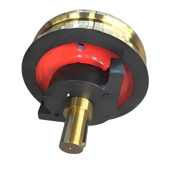
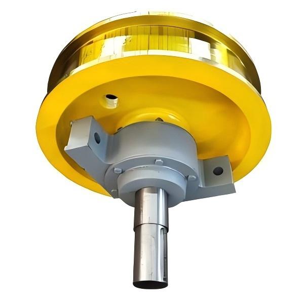
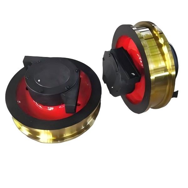
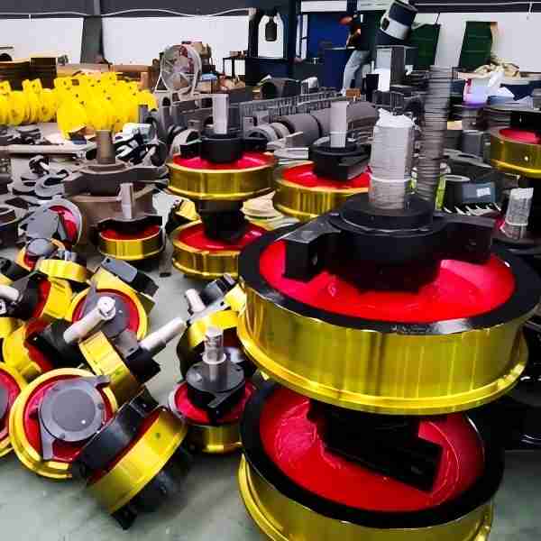
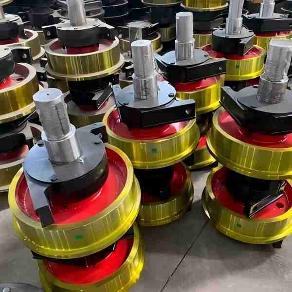
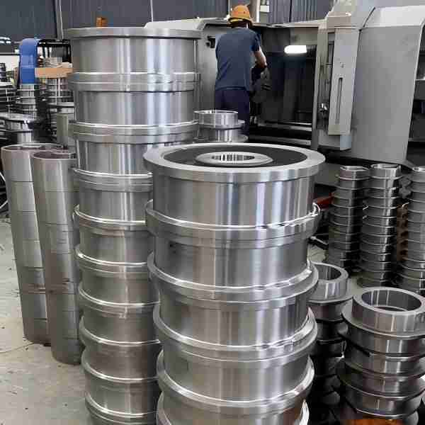
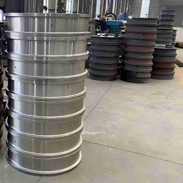
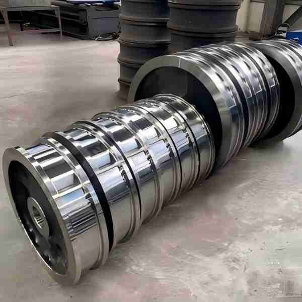
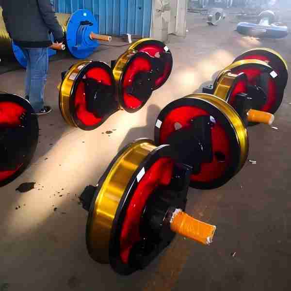
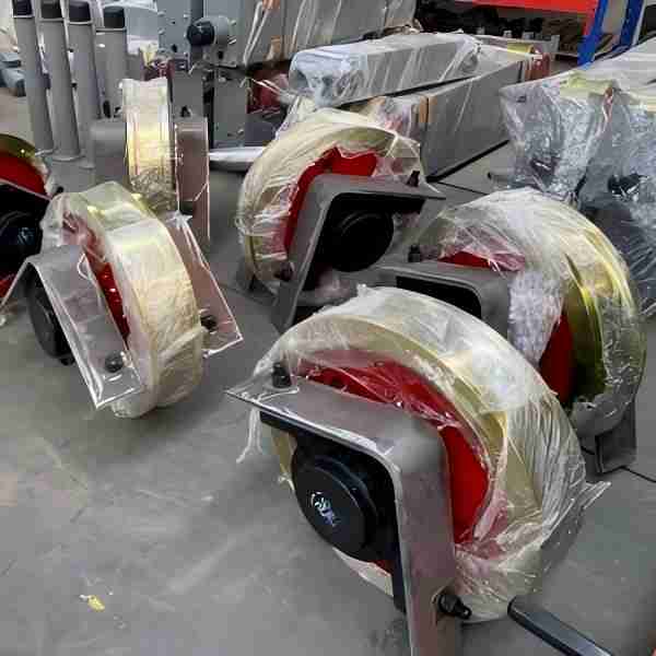
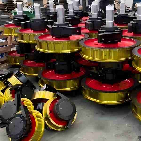
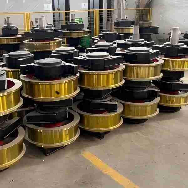
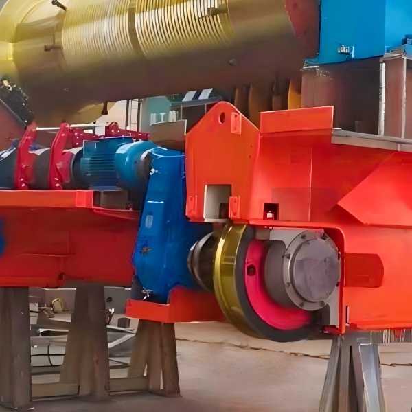
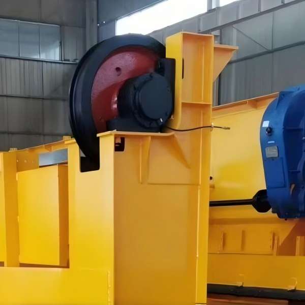
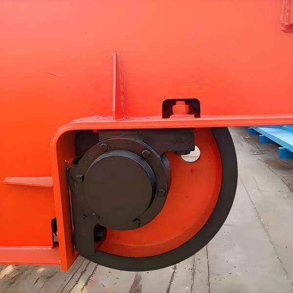
Angle bearing box crane wheel
Angle Bearing Box Crane Wheel Parameters:
- Specifications: Φ250, Φ350, Φ400, Φ500, Φ600, Φ700, Φ800
- Wheel Material: ZG430-640, 45 steel, 50SiMn, 65Mn, 42CrMo
- Wheel Type: Double flange, Single flange, No flange
- Wheel Groove Width: Determined according to track model
- Custom Orders: We can manufacture based on your drawings and dimensions provided.
The Angle Bearing Box Crane Wheel serves as an important mechanical component that supports lifting machinery and its loads, while enabling the crane to travel back and forth along the track. The design and manufacturing processes of this wheel set take into account multiple factors to ensure its performance and safety.
Wheel Set Applications:
The crane wheel set primarily serves on single and double girder cranes.
Depending on the crane’s tonnage and operating environment, the crane wheel set can be classified into the following types:
- For cranes with a tonnage under 50 tons: The main girder wheels feature a double-flange structure, equipped with seven-class tapered bearings. The bearing box utilizes an angular design, and each wheel set includes four bearings. The wheel tread is typically made of cast iron. For the trolley wheels, a single-flange structure is commonly used, with an angular bearing box and two seven-class bearings per wheel set. The wheels are made of cast copper.
- For large-tonnage cranes (50 tons and above): The main girder wheels typically use heavy-duty wheel sets with double-flange structure wheel treads. The bearing box can be either angular or circular in shape, usually made of cast copper. The bearings are of the third-class variety, and the wheels are made of either cast or forged material. For the trolley wheel set, a double-flange structure is also employed, with third-class bearings, and the bearing box is made of cast steel.
The design and manufacturing standards for the Angle Bearing Box Crane Wheel ensure the safe and stable operation of the lifting machinery, while also considering ease of maintenance and cost-effectiveness. This wheel set finds wide applications in various industrial and construction environments and is an essential component of lifting machinery.
Surface Wear Resistance of the Wheel Set:
The wear resistance of the wheel set’s surface plays a crucial role, as it directly influences its service life. Consequently, high-quality wheel sets undergo heat treatment on the tread. When the surface hardness reaches HB300-350, the service life of the wheel set increases significantly, making it a qualified wheel set.
Technical Parameters:
The technical parameters of the wheel set are crucial, as the alignment and level of the operating mechanism during use directly affect its performance. If the alignment is too far off, it can result in track wear, increased resistance, vibration, and significant noise pollution.
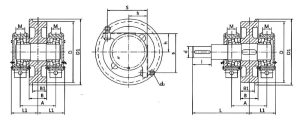
Single-Rim Wheelset
| Wheel diameter | Drawing No. | Size (mm) | ||||||||||||
| D | D1 | B | B1 | A | L | L1 | h | S | M | d | I | d1 | ||
| Φ250 | L754 | 250 | 280 | 90 | 70 | 180 | 237 | 130 | 80 | 180 | 30 | 45 | 82 | M20 |
| L755 | 250 | 280 | 90 | 70 | 180 | / | 130 | 80 | 180 | 30 | / | / | ||
| φ315 | L774 | 315 | 345 | 100 | 81 | 200 | 320 | 150 | 105 | 225 | 50 | 65 | 105 | |
| L775 | 315 | 345 | 100 | 81 | 200 | / | 150 | 105 | 225 | 50 | / | / | ||
| Φ350 | L756 | 350 | 380 | 100 | 81 | 200 | 320 | 150 | 105 | 225 | 50 | 65 | 105 | |
| L757 | 350 | 380 | 100 | 81 | 200 | / | 150 | 150 | 225 | 50 | / | / | ||
| φ400 | L758 | 400 | 440 | 120 | 100 | 240 | 365 | 170 | 120 | 260 | 50 | 80 | 130 | |
| L759 | .400 | 440 | 120 | 100 | 240 | / | 170 | 120 | 260 | 50 | / | / | ||
| Φ500 | L762 | 500 | 540 | 130 | 110 | 270 | 365 | 195 | 140 | 300 | 50 | 80 | 130 | |
| L763 | 500 | 540 | 130 | 110 | 270 | / | 195 | 140 | 300 | 50 | / | / | ||
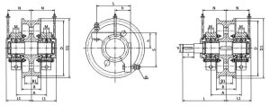
Double-Rim Wheelset
| Wheel diameter | Drawing No. | Size (mm) | ||||||||||||
| D | D1 | A | B | B1 | L | L1 | h | S | M | d | I | d1 | ||
| φ500 | L764 | 500 | 540 | 280 | 210/160 | 150/100 | 400 | 230 | 140 | 310 | 50 | 75 | 105 | M24 |
| L765 | 500 | 540 | 280 | / | 230 | 140 | 310 | 50 | / | / | ||||
| Φ600 | L766 | 600 | 640 | 280 | 210/160 | 150/100 | 415 | 230 | 140 | 310 | 50 | 85 | 130 | |
| L767 | 600 | 640 | 280 | / | 230 | 140 | 310 | 50 | / | / | ||||
| φ700 | L768 | 700 | 750 | 315 | 210/160 | 150/100 | 455 | 260 | 160 | 350 | 80 | 90 | 130 | M30 |
| L769 | 700 | 750 | 315 | / | 260 | 160 | 350 | 80 | / | / | ||||
| φ700 | L770 | 800 | 850 | 365 | 210/160 | 150/100 | 500 | 300 | 190 | 410 | 90 | 95 | 130 | |
| L771 | 800 | 850 | 365 | / | 300 | 190 | 410 | 90 | / | / | ||||
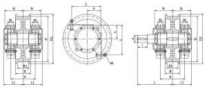
Heavy-Duty Wheelset
| Wheel diameter | Drawing No. | Size (mm) | ||||||||||||
| D | D1 | B | B1 | A | L | L1 | h | S | M | d | I | d1 | ||
| Φ600 | L174B | 600 | 650 | 210/160 | 150/100 | 325
325 |
470 | 255 | 180 | 390 | 70 | 95 | 130 | M24 |
| L175B | 600 | 650 | / | 255 | 180 | 390 | 70 | / | / | |||||
| φ700 | L176B | 700 | 750 | 210/160 | 150/100 | 360
360 |
500 | 280 | 200 | 440 | 80 | 110 | 165 | M30 |
| L177B | 700 | 750 | / | 280 | 200 | 440 | 80 | / | / | |||||
| Φ700 | L178B | 700 | 750 | 210/160 | 150/100 | 380
380 |
500 | 305 | 220 | 485 | 80 | 110 | 165 | |
| L179B | 700 | 750 | / | 305 | 220 | 485 | 80 | / | / | |||||
| φ800 | L196B | 800 | 850 | 210/160 | 150/100 | 380
380 |
500 | 305 | 220 | 485 | 80 | 110 | 165 | |
| L197B | 800 | 850 | / | 305 | 220 | 485 | 80 | / | / | |||||


